Skip to content

Blog

Adding Wireless Charging to HackHeld

Hackheld is a DIY, open-source, hackable handheld designed to be easy to build and customize. And with a simple mod, it can run on a battery. But here, we will go one step further and add Qi wireless charging!

Turns out it’s quite easy to do and cheap as well.

This might be obvious, but you need a HackHeld Vega II and the battery mod. You can get both at my online store:

And I highly recommend you get a nice transparent case with enough space for the battery and the wireless charging circuit:

You also need a wireless charging circuit. I used this one from AliExpress for 3€, but others work, too:

Once you have everything and the HackHeld is assembled and working, adding the wireless charging circuit is quite easy.

The wireless charging PCB has 2 wires. Red goes to VBUS, and Black goes to GND. You can also use a multimeter to double-check the polarity.

  • VBUS (red) is the same pin you soldered the little red from the battery mod to.
  • GND (black) is the pin next to it.

Back of HackHeld with soldered cables of wireless charging module

The wireless charging module came with a magnetic sticker. Use it to mount the coil to the case. Make sure that when you screw on the case, that nothing is pressing on the battery!

Back side of HackHeld with case next to it. Wireless charging module inside of case. Side view of assembled HackHeld

Now, you can put your HackHeld on a wireless charging pad and enjoy the success of having built something cool and modified it to be even cooler. HackHeld chilling on a ikea wireless charger

DIY USB Nova

To install the Nova firmware onto the Adafruit board, simply download the Trinkey uf2 file from the release page and copy it onto its boot drive. Details below.

In 2022 I made the USB Nova. You can read more about it in my other Blog post I made a BadUSB. But the short version is it’s an HID injection tool, much like the famous USB Rubber Ducky and other pentesting devices. But the Nova is Open Source and easier to use.

Like always, I try to build my tools so that it’s easy to recreate them with easily accessible components. So here’s the long overdue tutorial on how to make your own USB Nova using the Adafruit Trinkey QT2040 development board.

Adafruit Trinkey QT2040, 3D printed case, and screws

The Trinkey is a development from Adafruit that’s based on the RP2040.

It’s perfect for the USB Nova firmware because it already comes with a USB-A Plug, 8MB of flash, an RGB LED and a boot button that we can use to start scripts.

You don’t need to solder anything to the board, and you don’t need a cable. All you have to do to use it as a BadUSB is to flash the USB Nova firmware.

I even designed a simple case for it: https://www.printables.com/model/533853-adafruit-trinkey-qt2040-case (Requires 4x M2.5 3mm screws)

Of course, you could also use any other RP2040 dev board, but this one doesn’t require any modifications. Most other boards don’t support repurposing the boot button, so you’d have to solder a switch on.

  1. Plug the Trinkey into your computer while holding the BOOT button.

Trinkey being plugged into the computer while holding the boot button

  1. The RPI-RP2 drive should appear on your computer. (If it doesn’t, try again)

  2. Download the latest USBNova_diy_trinkey_.uf2 file from the release page

USB Nova firmware release page

  1. Copy the downloaded uf2 file onto the RPI-RP2 drive. The Trinkey will update itself and reconnect.

Copied USB Nova firmware uf2 file on the RPI-RP2 drive

  1. Done! To run a script, press the boot button for 1 second.

Yep, it is that easy! Download and drag the uf2 firmware file onto the Trinkey boot drive, and you have a USB Nova.

For instructions on how to use the USB Nova, check the documentation.

One thing to remember is that with this board, you don’t have an attack mode switch. Instead, it will always start in setup mode, and by pressing the Trinkeys boot button, you begin the attack. Unfortunately, there is no way to start the DIY Nova in attack mode.

If you like this project, please consider buying a USB Nova or something else from spacehuhn.store to support my open-source hacking endeavours. Developing, documenting, manufacturing, distributing, and maintaining these tools is a ton of work.

Thanks! ❤️

New HackHelds

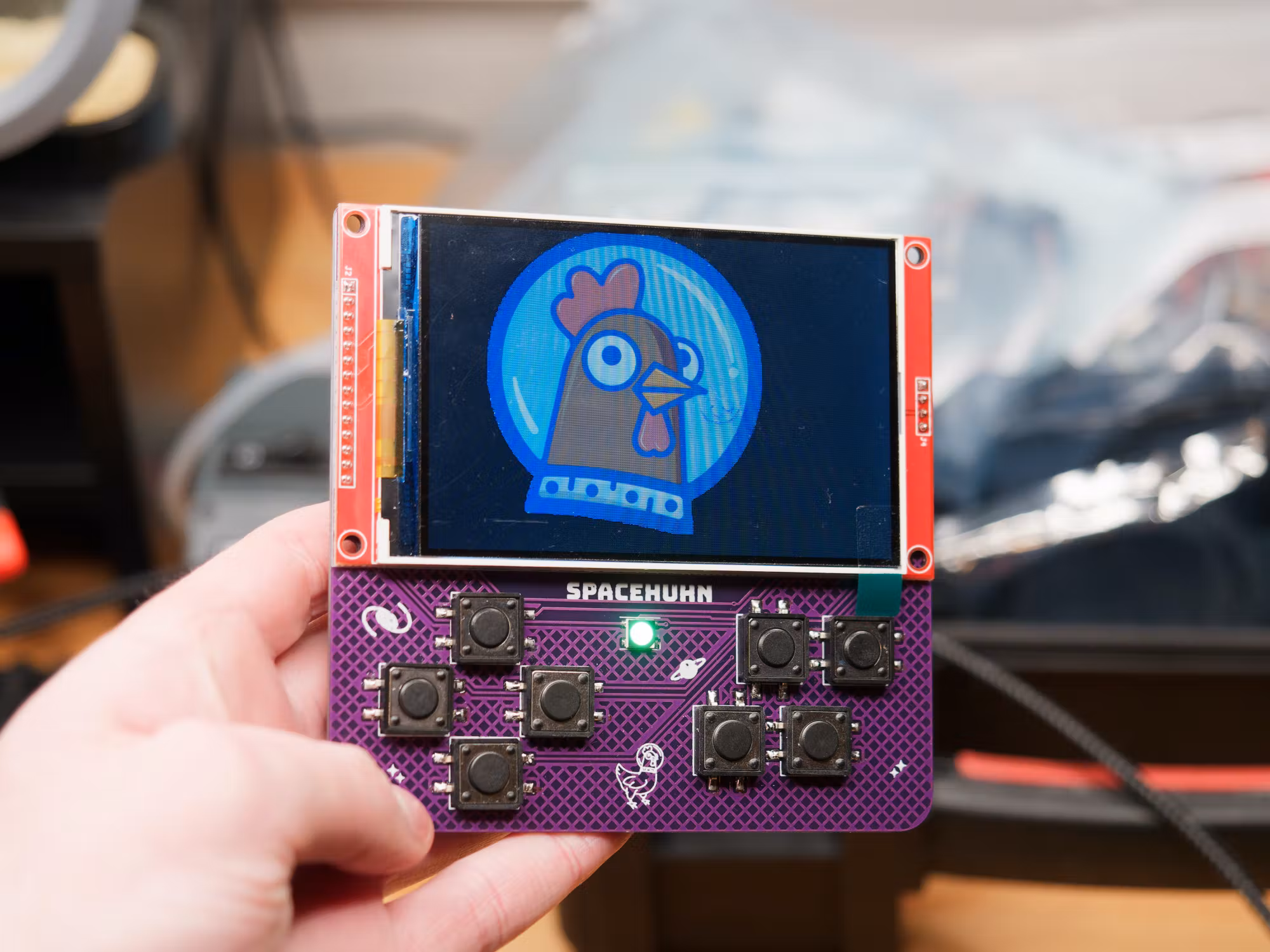
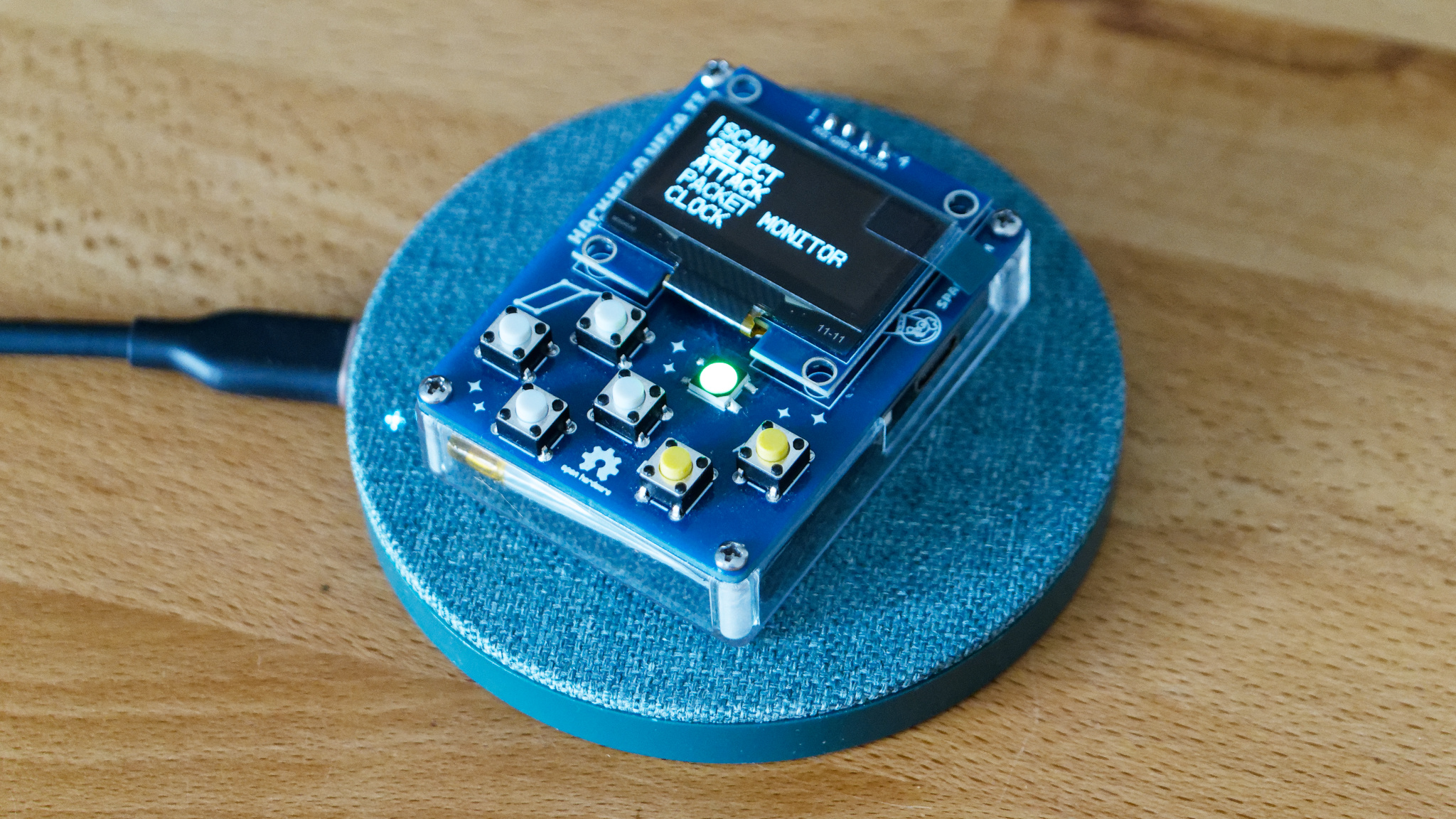
The HackHeld is a DIY open-source hackable handheld I released in 2021. It’s a simple PCB design that you can use to build your own Deauther.

I originally envisioned more than one design but unfortunately lost interest in the project at the time. However, now that I’ve invested more time into hardware design, I felt compelled to give my old design ideas another chance.

Here’s what I’ve learned from it. 😊

At first, I was unsure about the display choice. So I went ahead and ordered a bunch of LCDs. I might have overdone it when I decided to buy one of each size I could find. 😅

My Arduino LCD collection

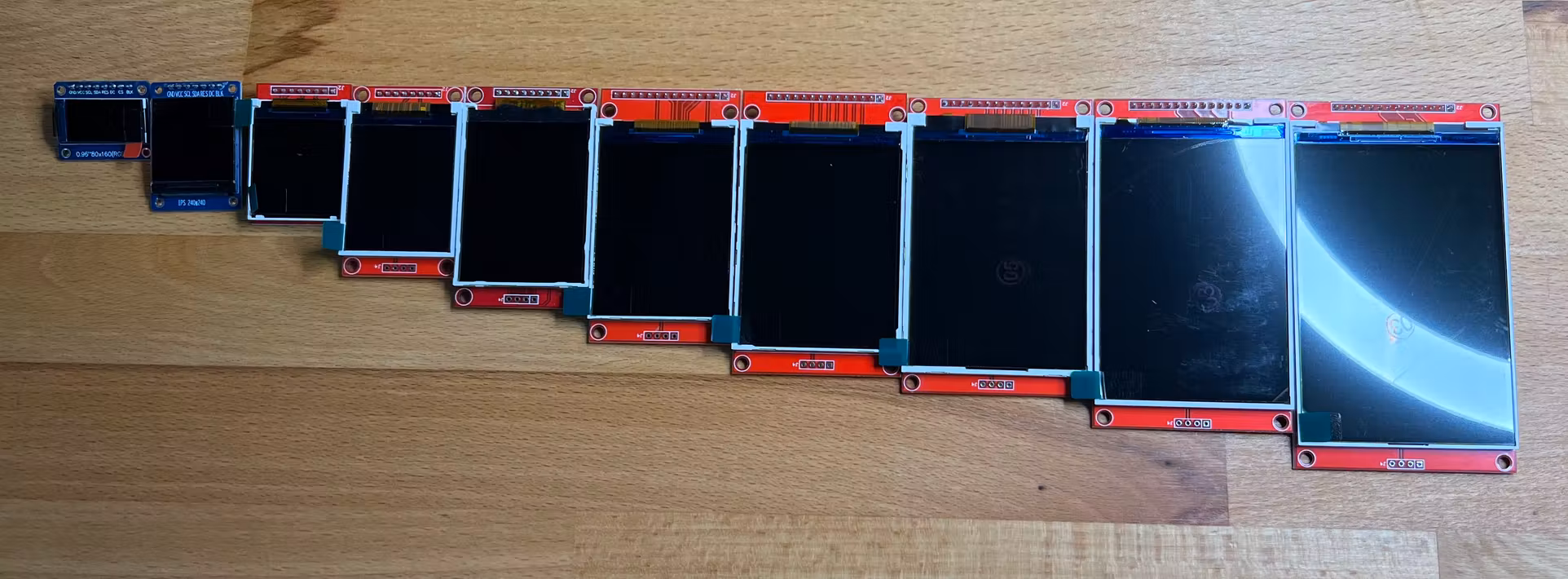
The OLED screen I’ve used for the HackHeld Vega is great, but it only comes in 0.96” and 1.3”. So I wanted to try out some LCDs, which come in various sizes and resolutions. Of course, this makes it a lot harder to choose. But experimenting is what this whole endeavour is for. So I started designing!

HackHeld mini PCB 3D render

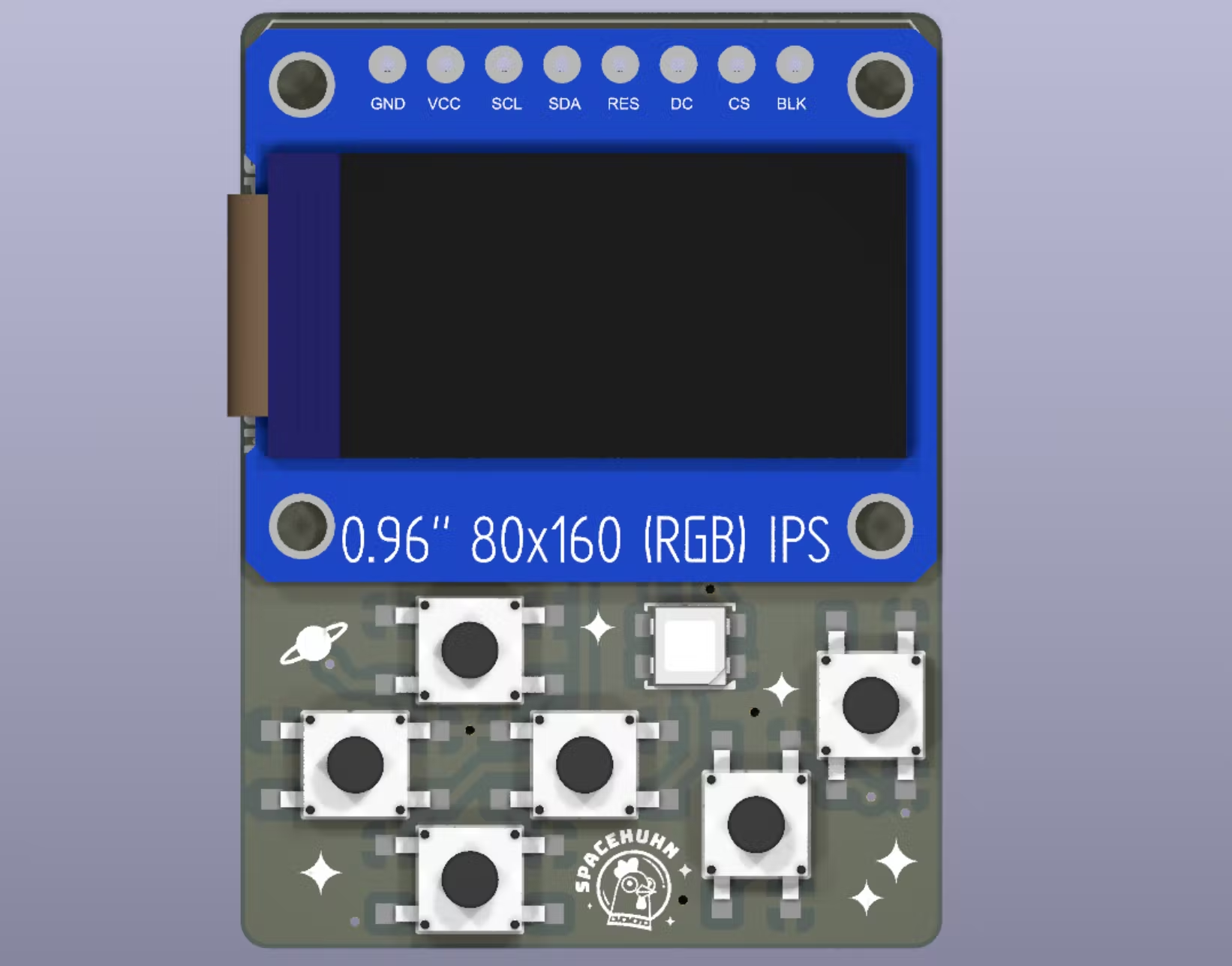
I made a mini version using a 0.96” LCD.

HackHeld 4 inch PCB 3D render

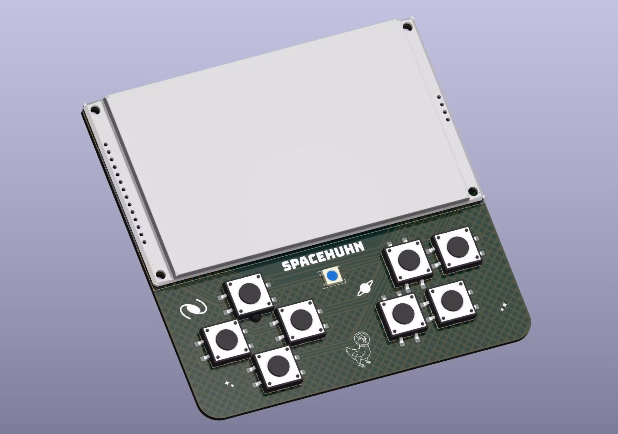
And I made a gigantic 4” version because I couldn’t not use the largest LCD I had just bought.

HackHeld Vega 2 3D render

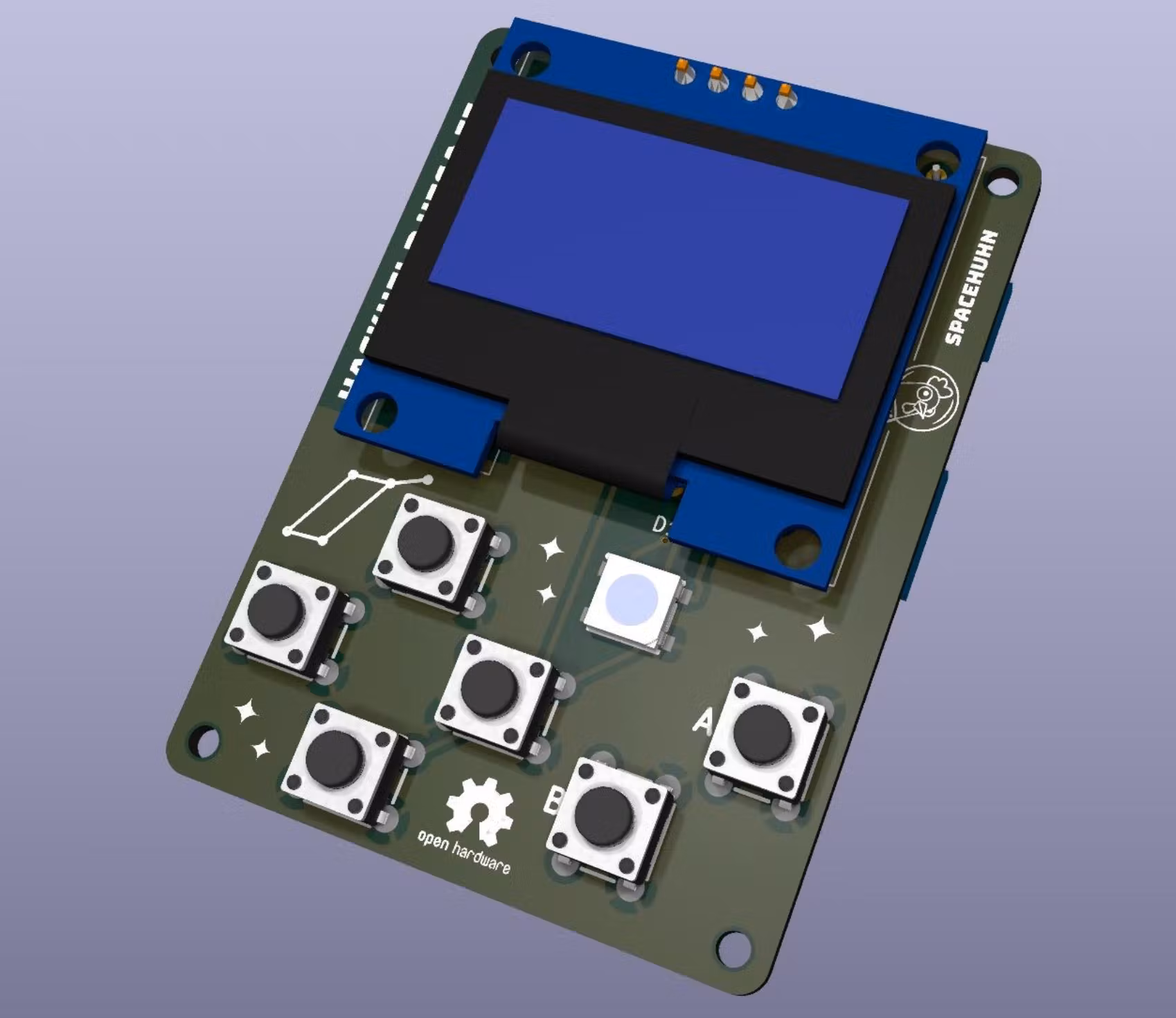
I also updated the Vega to make it smaller and fix some design flaws.

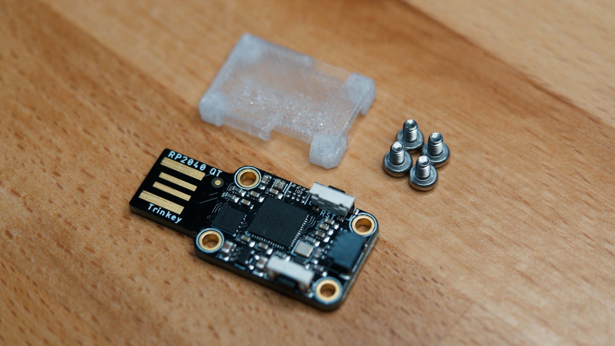
One thing to remember is that the whole idea behind the HackHeld Vega was to make it as easy and cheap as possible. This means using components that are easy to source from marketplaces such as AliExpress, eBay, or Amazon.

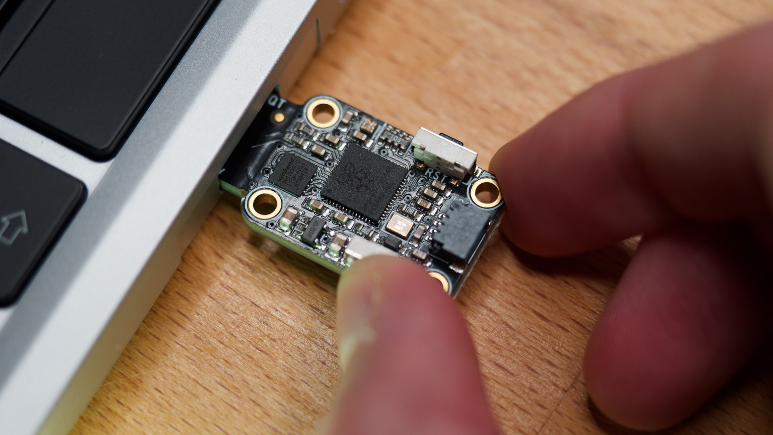
It also means using development boards and display breakouts, as they are easy to solder and use.

Hackheld Vega Parts

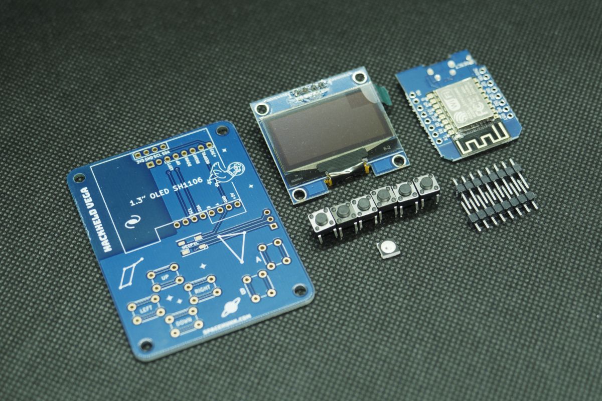
Some people have criticised this choice, but the HackHeld Vega was never meant to be a product for mass production. It’s an open-source DIY project for beginners. The barrier of entry is intentionally low, with all associated disadvantages. Those who know how to solder ribbon cables and SMD components don’t need a project like this. They can make their own Deauther without help.

And while I don’t want to restrict myself to these rules, I applied the same dev board approach to the new designs to see how far I could get given the limitations.

HackHeld Vega II Prototype

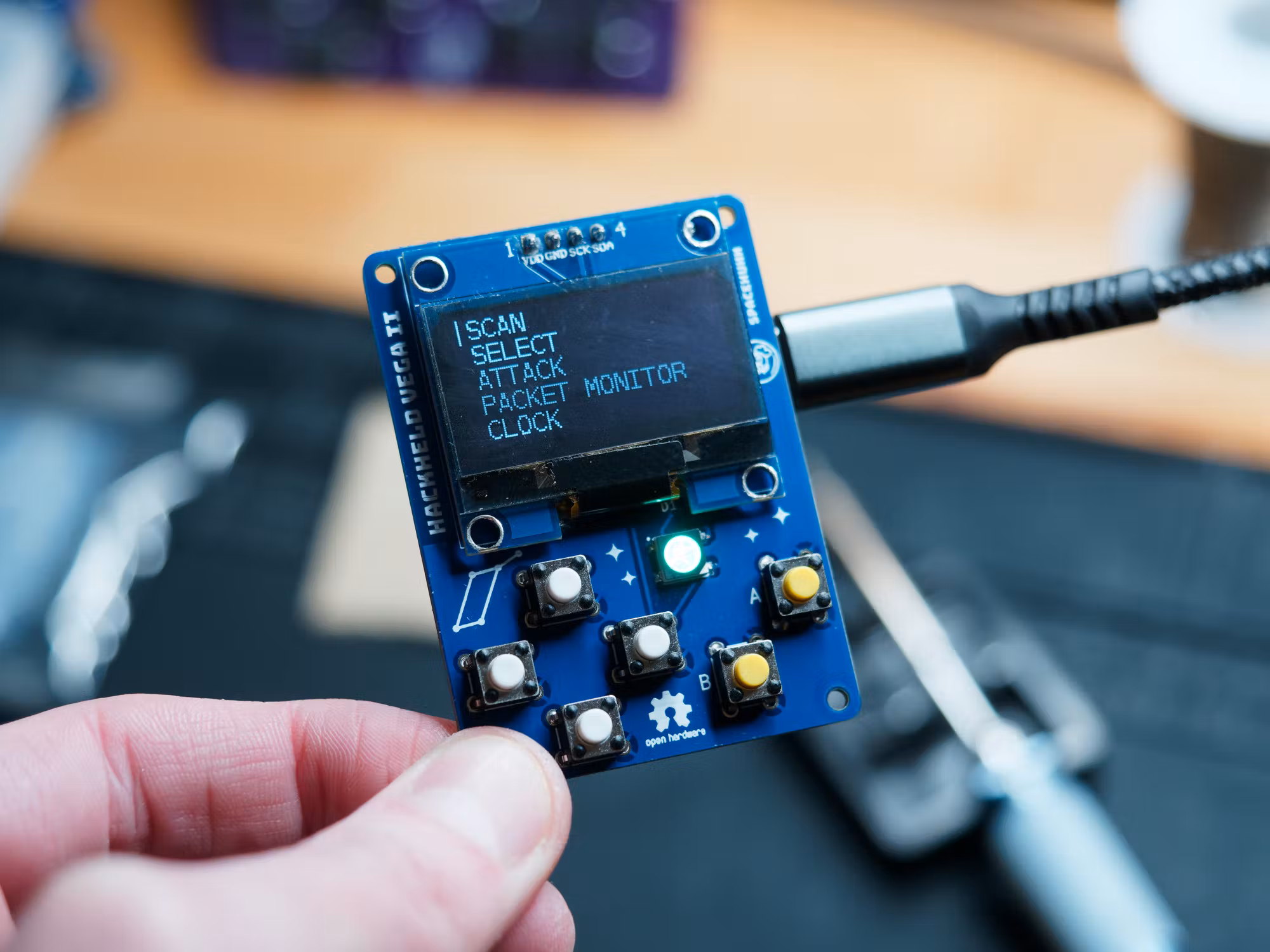
I’m most happy about the updated Vega design. Although I still have to design a new case for it.

HackHeld Mini Prototype

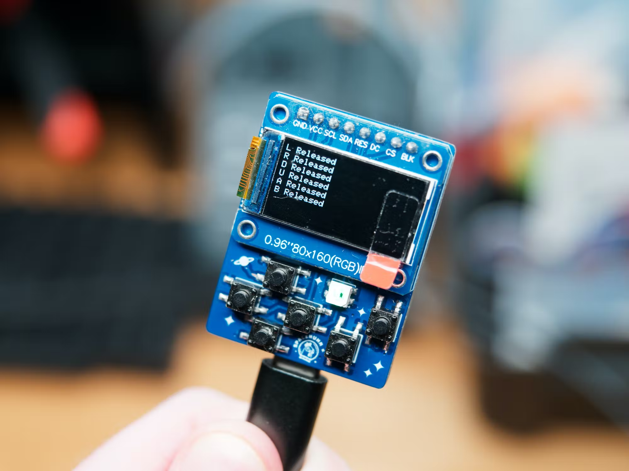
The mini HackHeld is cute, and I like the form-factor. But it’s not easy to solder, so I think I’ll turn this design into a fully custom-made product without the breakout board approach. This way, I can add battery support and other cool features. And it can still be a DIY project for those who like to train their SMD soldering skills.

HackHeld XL Prototype

And the XL version - I honestly don’t know what to do with it. It looks absolutely stunning. But I don’t have any cool firmware for it yet. So it feels like a project I will have to put on pause to pick it up later when I have another project to combine with. The gigantic design has a lot of disadvantages for beginners also. The PCB is a lot more expensive, and the LCD is almost $20. Not to mention the feather board I used to drive this many buttons and add battery support.

Making handhelds is fun!

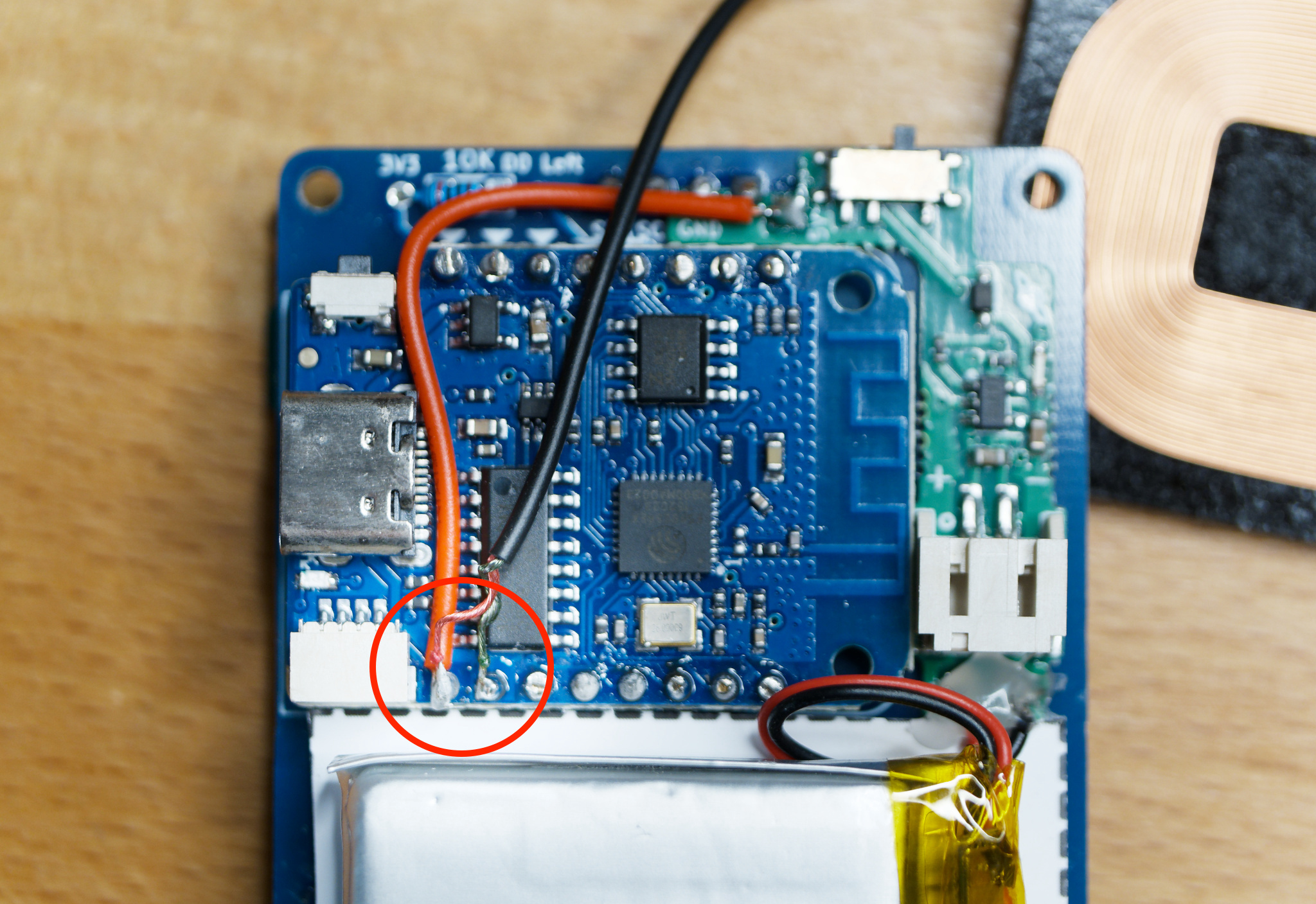
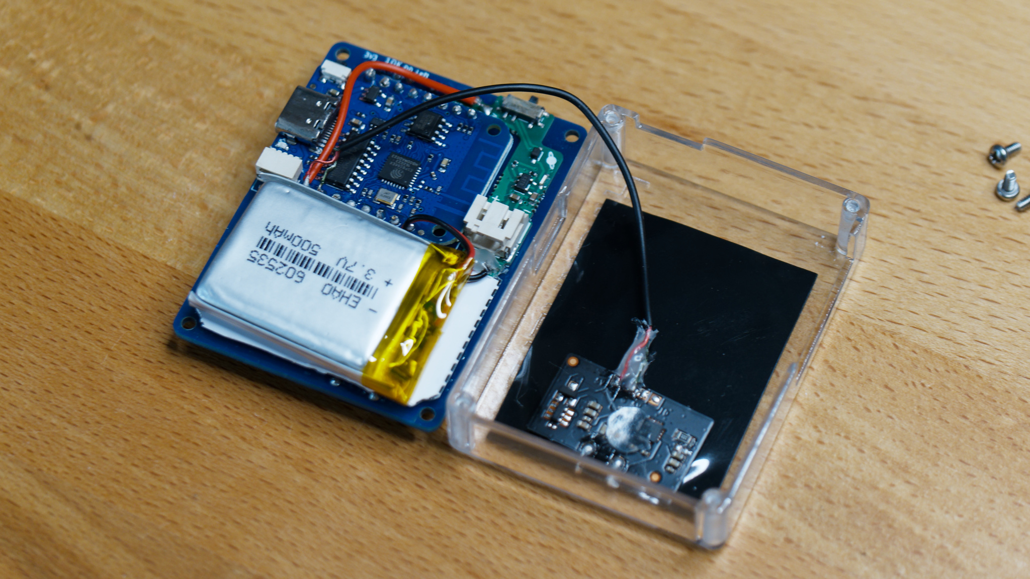
They look cool, and dev boards and breakouts drastically reduce cost, development, and assembly time. But it comes with a few disadvantages. For example, the HackHeld Vega does not have battery support. Of course, you can hack something to add it, but it’s not ideal.

I will release the updated Vega design and add it to my store as soon as it’s finished. But the other designs need a lot more time and thought. As of right now, I have no firmware for them. It’s a cool-looking piece of hardware but completely useless. So I will work on other projects to make something interesting that makes sense to combine with these cool handheld designs.

I hope this little insight into my work process was interesting to you! 😊

How to install ESP8266 Deauther (.bin)

Want to build an ESP8266 Deauther? Here is the official installation guide using .bin files. This installation method is the easiest. But if you’re looking to modify the code, follow the Arduino IDE tutorial.

The ESP8266 Deauther is a popular open-source pen-testing tool. You can test your own WiFi network against the common denial-of-service vulnerability called deauthentication attack. You can also use it to create the appearance of a lot of WiFi networks that are not really there to learn and experiment with WiFi.

And the best part, all you need is an ESP8266! Not sure which one to get? We made a post about development boards we recommend: Recommended Dev-Boards for Deauther

  1. Get a .bin file for your board

  2. Open esptool.spacehuhn.com in Chrome, or another supported browser

  3. Connect your ESP8266 board via USB

  4. Click Connect and select the serial port of your ESP

  5. Select your Deauther .bin file

  6. Click Program

Animated ESP Web Tool workflow GIF

If you don’t know which serial port to select, click connect on esptool.spacehuhn.com and then plug in your board. Whatever port pops up in the list is what you’re looking for.

You should check the cable and USB port if no new port pops up. Some USB cables are only for charging and cannot transmit data.

Or maybe you’re missing the drivers for your device:

🔗 CH340/CH341 Drivers: http://www.wch-ic.com/downloads/CH341SER_ZIP.html
🔗 CP210x Drivers: https://www.silabs.com/developers/usb-to-uart-bridge-vcp-drivers
🔗 FTDI Drivers: https://ftdichip.com/drivers/

Make sure to set the baud rate to 115200 in the settings. Higher baud rates allow faster upload speeds but can also introduce connection issues.

If that doesn’t help, check out this blog post about common ESP8266 and ESP32 errors: /blog/espcomm/

And if you run into other issues, try using a different flashing tool/method.

My ESP web tool is not the only software you can use to flash your ESP8266:

And if you’re looking for something Deauther-specific, check out n2d: https://github.com/realmrvodka/n2d/

Now that you installed the Deauther firmware visit the documentation to learn more about the tool and how to use it.

I made a BadUSB

The USB Nova is an Open-Source BadUSB project. It looks like a cute colorful USB drive, but it’s a sort of programmable keyboard, much like the USB Rubber Ducky, WiFi Duck, and other BadUSBs.

USB Novas

USB Nova modes

Besides looking cool, it also makes scripting a lot easier!
You safely select between setup and attack mode with a little switch on the side.

USB Nova drive

It supports USB mass storage right out of the box. So when in setup mode, you can drag and drop scripts onto its drive.
No SD card or WiFi connection is required!

USB Nova preferences changing keyboard layout

This also allows you to change settings like the keyboard layouts, USB VID & PID, and other things effortlessly.

I also added a couple of new scripting functions and Mouse support.

So obviously, this is one of many products like this. I also made the WiFi Duck and worked on the MalDuino firmware.

Different BadUSBs)

But I was unhappy with how boring most BadUSBs are. I get it. They should look like a regular USB drive, so people who find them plug them in. But most people don’t want to drop their hacking toy somewhere. At least my community is full of young people interested in hacking who want to learn how these things work, try it out for themselves, or build their version of it. So there is no point in trying to sell them expensive gear made for companies and professional pentesters.

So I hope this little USB Nova lowers the entry bar a bit further, makes tinkering with HID injection attacks easier, and encourages a healthy hacker mindset.

Duckify Blog

If you don’t need features like USB mass storage, you can also build your own BadUSB! Check out my tutorial on how to make one with a $3 Digispark

duckify.spacehuhn.com is an online script converter I made for turning BadUSB script into Arduino sketches while also taking care of the keyboard layout at the same time!