Display & Button Setup
Before you continue
Section titled “Before you continue”Using the display interface is entirely optional. You can also control the Deauther via serial or the web interface.
We cannot start at 0 for this tutorial, so if you find this too tricky, get an Arduino starter kit with good documentation to get a feeling for tinkering with electronics. 😊
I focused on the NodeMCU in this tutorial since it is one of the most popular dev-boards. But every other ESP8266-based board should work just the same.
What you need
Section titled “What you need”- A breadboard (Amazon*, AliExpress*)
- Jumper wires (Amazon*, AliExpress*)
- An ESP8266 dev board (see Supported Devices) (Amazon*, AliExpress*)
- At least 3 buttons (3 are required, optionally up to 6) (Amazon*, AliExpress*)
- An SSD1306 or SH1106 OLED display with 128x64 pixels (other resolutions are not supported) (Amazon*, AliExpress*)
- Optional: an RGB LED (3 single LEDs or a Neopixel will also work) (Amazon*, AliExpress*)
- Optional but recommended: 2x 10k ohm resistors (Amazon*, AliExpress*)
- A working Arduino IDE setup that can compile this project (see Installation)
*Affiliate Links
Wire everything up
Section titled “Wire everything up”Look up the pinout references for your board. Here’s one for the NodeMCU:
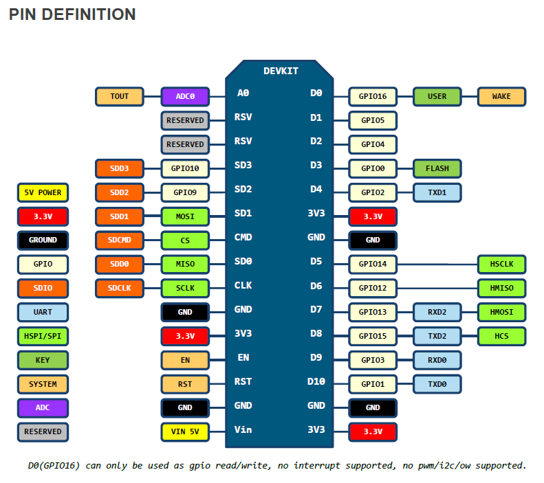
We have a limited amount of pins, and not every pin can be used for everything:
| NodeMCU Pin | GPIO | Note |
|---|---|---|
| D0 | GPIO 16 | No I2C or PWM. Don’t use this pin for the RGB LED or Display. |
| D1 | GPIO 5 | OK |
| D2 | GPIO 4 | OK |
| D3 | GPIO 0 | Connected to flash button. |
| D4 | GPIO 2 | Needs pull-up resistor. |
| D5 | GPIO 14 | OK |
| D6 | GPIO 12 | OK |
| D7 | GPIO 13 | OK |
| D8 | GPIO 15 | Needs pull-down resistor |
| D9 | GPIO 3 | RX (Serial). Avoid this pin. |
| D10 | GPIO 1 | TX (Serial). Avoid this pin. |
| SD2 | GPIO 9 | Used for Flash. Avoid this pin in QIO mode. |
| SD3 | GPIO 10 | Used for Flash. Avoid this pin in QIO mode. |
Display
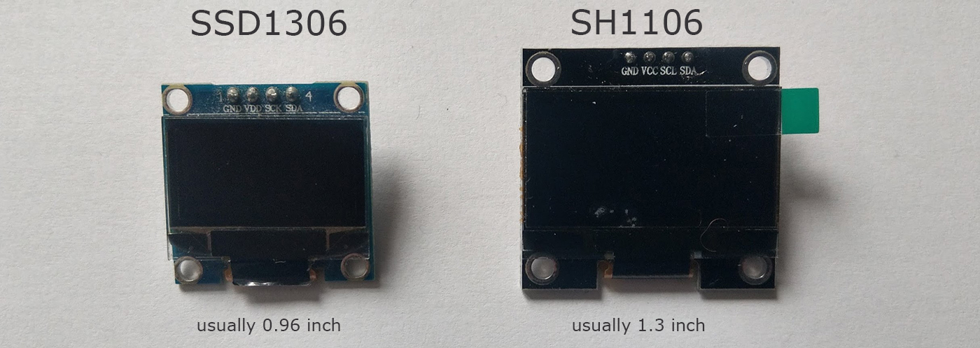
Section titled “Display”2 types of OLED displays can be used for this project. The SSD1306, and the SH1106:
And they are available in I2C or SPI versions:
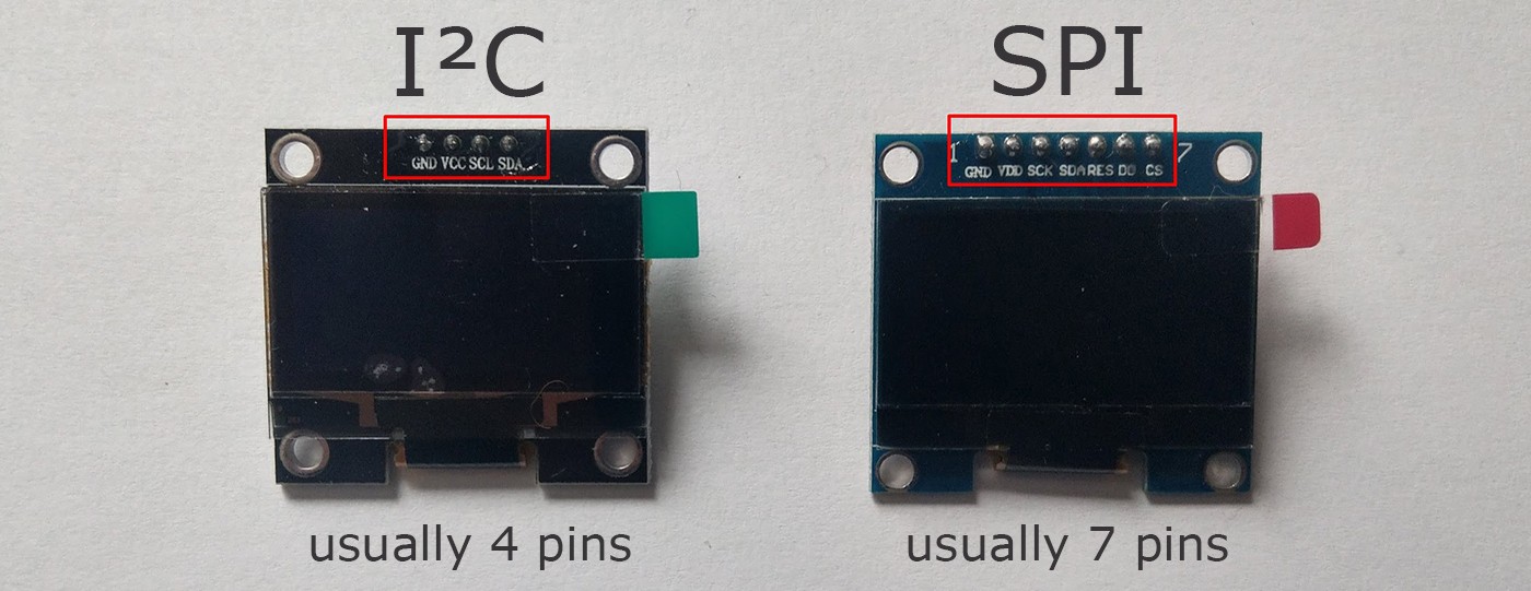
I2C can be connected to any GPIO pin (except 16).
SPI, however, requires the following setup:
| Display | GPIO |
|---|---|
| SCL/CLK/SCK | GPIO 14 (D5) |
| SDA/MOSI | GPIO 13 (D7) |
RST, DC, and CS pins can be connected to other pins.
Buttons
Section titled “Buttons”Connect each button to a GPIO and GND. Like in this Arduino tutorial: https://www.arduino.cc/en/Tutorial/InputPullupSerial
The LED is used as an optional indicator. For example, Green = idle, Blue = scanning, and RED = deauth attack detected (when scanning).
You can use single digital LEDs, an RGB LED, or a Neopixel LED (WS2812b).
By default, the LED on GPIO 16 (NodeMCU onboard LED) and the LED on GPIO 2 (ESP-12 and ESP-07 on-module LED) are used.
Example setup with I2C OLED
Section titled “Example setup with I2C OLED”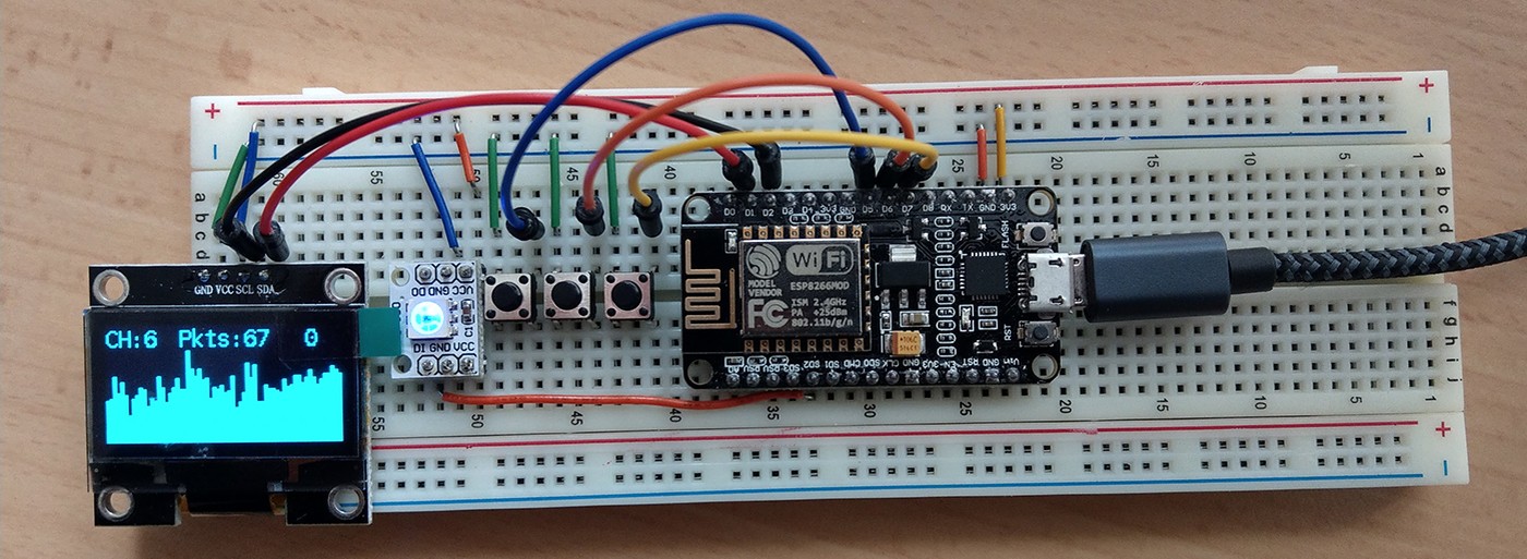
| Display | GPIO |
|---|---|
| GND | GND |
| VCC/VDD | VCC / 3.3V |
| SCL/CLK/SCK | GPIO 4 (D2) |
| SDA | GPIO 5 (D1) |
| Button | GPIO |
|---|---|
| UP | GPIO 14 (D5) |
| Down | GPIO 12 (D6) |
| A | GPIO 13 (D7) |
| NEOPIXEL LED | GPIO |
|---|---|
| GND | GND |
| VCC | VCC/3.3V |
| DIN | GPIO 9 (SD2) |
Example setup with SPI OLED
Section titled “Example setup with SPI OLED”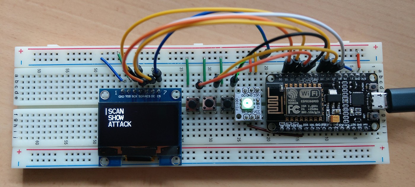
| Display | GPIO |
|---|---|
| GND | GND |
| VCC/VDD | VCC / 3.3V |
| SCL/CLK/SCK | GPIO 14 (D5) |
| SDA/MOSI | GPIO 13 (D7) |
| RST/RES/RESET | GPIO 5 (D1) |
| DC | GPIO 4 (D2) |
| CS | GPIO 15 (D8) or GND |
| Button | GPIO |
|---|---|
| UP | GPIO 0 (D3) |
| Down | GPIO 12 (D6) |
| A | GPIO 2 (D4) |
| NEOPIXEL LED | GPIO |
|---|---|
| GND | GND |
| VCC | VCC/3.3V |
| DIN | GPIO 9 (SD2) |
Code adjustments
Section titled “Code adjustments”When your hardware setup is done, you must make some code changes.
-
See Installation on how to compile and flash this project using Arduino.
-
In Arduino, under
tools>Deauther Config, selectDisplay Example I2CorDisplay Example SPIdepending on your setup -
In Arduino open the
A_config.hfile (second tab) -
Scroll down to
#if defined(DISPLAY_EXAMPLE_I2C)or#elif defined(DISPLAY_EXAMPLE_SPI). -
If you used other pins than mentioned in the example setup above, this is where you can change them.
For example, you might need to change#define SH1106_I2Cto#define SSD1306_I2Cdepending on the display you are using.
Or#define SH1106_SPIto#define SSD1306_SPIif you’re using an SPI display. -
In Arduino, under
tools>Erase Flash, selectAll Flash Contents. This will make sure your changes are applied and override any old settings. -
Make sure you selected the correct port and upload! If something isn’t working correctly, check the connections and your adjustments from step 5.
Testing everything
Section titled “Testing everything”When everything is correctly set up and uploaded, open the serial monitor with Arduino (Tools > Serial Monitor).
-
Set the baud rate to
115200and selectNewline. If you see it resetting every few seconds, check the code and make sure you didn’t use the same pin twice. -
If there’s no image on display, type
set display true;;save settingsand press enter. Now press the reset button on the board to restart it. If the display doesn’t show anything, something is off. Check your connections and the code. -
To test all buttons, enter
screen mode buttontest. To get back, usescreen mode menu. -
To test the LED(s), you can run
led <r> <g> <b>. For example,led 255 0 0should turn the LED red.
If you still have problems with the display, try running an example to test if it’s a software or a hardware problem. This is the display library used in the Deauther: https://github.com/squix78/esp8266-oled-ssd1306
You can find examples there. Try to get those running.