Connections
Example Setup
Section titled “Example Setup”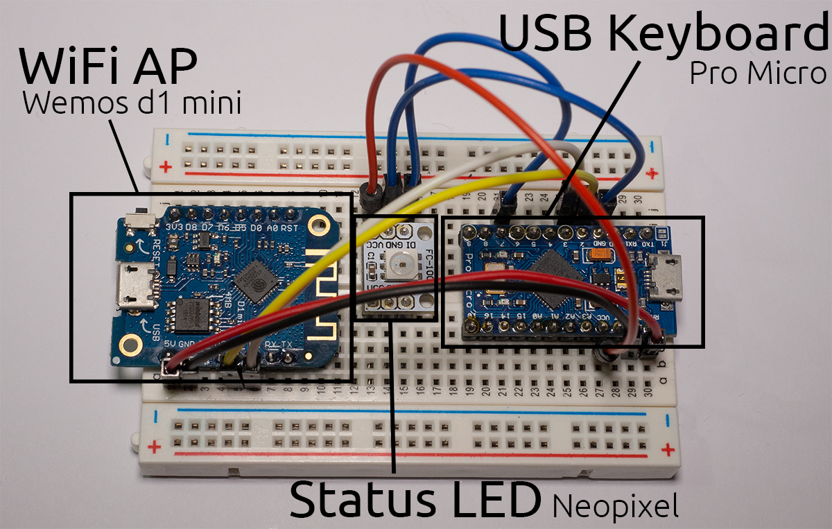
Main connections
Section titled “Main connections”Connect these pins between the two boards:
| ESP8266 | Atmega32u4 |
|---|---|
D1 aka. GPIO 5 | 3 aka. SCL |
D2 aka. GPIO 4 | 2 aka. SDA |
GND | GND |
Sharing power
Section titled “Sharing power”Ideally, you want the Atmega32u4 to power the ESP8266, so it can run on one USB connection instead of always having to plug in both. To share power between them, you need a voltage regulator to provide 3.3V for the ESP8266. Luckily most boards have such a regulator on board.
| ESP8266 Dev Board | Atmega32u4 |
|---|---|
5V or VIN | RAW, 5V or VIN |
Adding the LED
Section titled “Adding the LED”To add a Neopixel (WS2812b) LED:
| Atmega32u4 | Neopixel LED |
|---|---|
7* | DI aka. Data, In |
5V aka. VCC | 5V aka. VCC |
GND | GND |
* The Data pin can be changed later in the software. Pin 7 is just an example.